The idea originated from a car sensor that alerts drivers when they are too close to an object while trying to park in a tight spot. I found this: JSN-SR04T. In contrast, I’m not sure whether the JSN-SR04T matches the quality of manufacturer-installed sensors; however, that’s not the point. I want to use a ~120×160 TFT display, a step-down voltage regulator(for a car battery to reduce voltage), and an Arduino Nano to process data from the sensor. Also, for Arduino Nano, the 8-channel level shifter is required to reduce 5V to 3.3V for the TFT display. For the ESP Arduino Nano version, a Level Shifter is not needed.
Parts
- JSN-SR04T ultrasonic proximity sensor
- The Arduino Nano | Documentation
- Waterproof DC Buck Converter Voltage Regulator 8-22V to 3-15V 5V 12V 3A
- It’s a DC-DC buck converter that takes a higher voltage input (8V to 22V) and steps it down to a lower voltage output, like 3V, 5V, 12V, etc. It’s called a buck converter because it only steps the voltage down, not up.
- TFT – ST7735S 128×160 display
- SN74LVC245AN – Arduino Nano: The digital pins run at 5V. Use a logic shifter to convert a 5V signal to 3.3V. I used an 8-channel shifter because a 4-channel one was not available for purchase at the time I bought the rest of the components.
- 18-Gauge Wire if planning to install it on the car.
Attempt Number 1
Logic Shifter
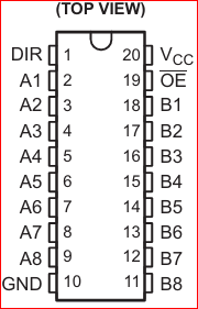
The SN74LVC245AN chip converts the 5V digital signals from the Arduino’s digital pins (connected to pins A1 through A8) and outputs them on pins B1 through B8 with a safe 3.3V logic level, provided the chip is powered with 3.3V on its Vcc pin(20).
- Pin 1: DIR (Direction)
- Connect this pin to 3.3V or 5V to set it HIGH(1), which enables data flow from A-side (input) to B-side (output).
- If the DIR pin is connected to GND, it is set LOW(0), and the direction is reversed — data flows from B-side (input) to A-side (output).
- In digital circuits, a HIGH signal (1) can turn a component or output ON, while a LOW signal (0) turns it OFF.
- Pin 19 OE (Output Enabled)
- Connect this pin to the common GND.
- Pin 20 Vcc
- IC power in this case is 3.3V from Arduino. Shifts 5V inputs from (A) down to 3.3V-safe signals for the TFT or sensor side (B).
Sensor JSN
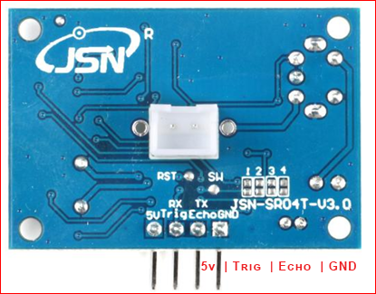
- From left to right:
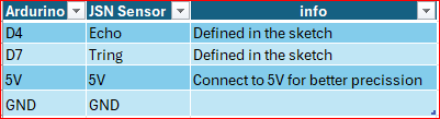
- 5v – ardurion 5v pin. It powers the sensor and needs to be plugged into a 5V. NOTE: I’ve had it connected to 3.3V, but from discovery, the measurement might not have been precise due to the lower voltage. So, keep it at 5V.
- Trig – Emitting an ultrasonic pulse. It needs to be defined in sketch.
- Echo – Listening for the echo from a nearby object. Calculated and needs to be defined in the sketch.
- GND – Common GND connected to Arduino.
TFT Display
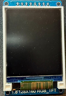
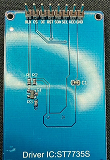
Pin from left to right
- BLK
- CS
- DC
- RST
- SDA
- SCL
- VDD
- GND
- BLK – BackLight Control
- It controls whether the screen’s LED backlight is on or off.
- Connected to GND wire – Backlight stays off (dark screen)
- Connected to 3.3V or 5V wire to Arduino – Backlight stays on (bright screen)
- Connected to a PWM pin – control brightness via software. Arduino can be connected to: Pin 3, 5, 6, 9, 10, and 11
- Syntax:
analogWrite(pin, value); // any pin from above | value 0 (off) 255 full brightness.
- It controls whether the screen’s LED backlight is on or off.
- CS – Chip Select
- The control signal used in SPI communication. NOTE: SPI is a pre-defined library.
- Library:
#include <SPI.h> - NOTE: About control signal, it can also be used
- TFT displays
- SD cards
- Sensors
- Shift registers
- Library:
- Pin-10 needs to be defined in the sketch
- The control signal used in SPI communication. NOTE: SPI is a pre-defined library.
- DC – Data Command
- It tells the TFT screen what kind of information is being sent over SPI:
- LOW (0V) → You’re sending a command (like clear screen, set color mode)
- HIGH (3.3V or 5V) → You’re sending data (like pixels, characters)
- Pin-9 and its connected to level shifter logic to reduce the voltage from 5V from Arduino to 3.3V on the B end of the chip.
- Pin-9 needs to be defined in the sketch
- It tells the TFT screen what kind of information is being sent over SPI:
- RST — When initializing the TFT screen, the Arduino briefly sets the RST pin LOW (0V) and then HIGH (3.3V) again (via a level shifter if required). This pulse resets the screen and ensures it starts in a known state.
- Pin-8 needs to be defined in the sketch
- SDA – Serial Data Line (don’t know why)
- Defined in library (Adafruit_ST7735) = pin 11
Adafruit_ST7735 tft = Adafruit_ST7735(TFT_CS, TFT_DC, TFT_RST);
- Defined in library (Adafruit_ST7735) = pin 11
- SCL – Serial Clock Line
- A timing line that keeps data transfer in sync.
- Without this pin, the display wouldn’t know when to read the bits from the data line.
- Library
#include <Adafruit_ST7735.h>= pin 13Adafruit_ST7735 tft = Adafruit_ST7735(TFT_CS, TFT_DC, TFT_RST);
- VDD – Power. It powers the TFT screen, and the positive wire needs to be connected to Ardurino 3.3V pin
- GND – Ardurion common ground pin
Pin Mapping Logic Level Shifter | TFT | Arduino
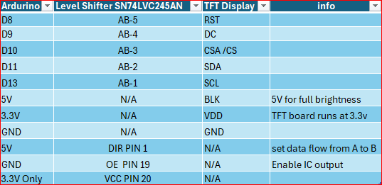
Note: The Logic Shifter pin 10 is connected to the Arduino Nano’s GND.
Pin Mapping JSN Sensor | Arduino
Code
// Library
#include <SPI.h>
#include <Adafruit_GFX.h>
#include <Adafruit_ST7735.h>

// Sensor Pins
#define trigPin 7
#define echoPin 4

// === Display pin D10 D8 D9
#define TFT_CS    10
#define TFT_RST   8
#define TFT_DC    9

// === Timing Control ===

//Define lastUpdate variable to 0 counter in milliseconds.
//Long defines memory space for Arduino to 32-bit.
//Unsigned the defined variable to be a positive number.
unsigned long lastUpdate = 0;
//Milliseconds between screen updates
const unsigned long updateInterval = 300;
//Stores the last measured distance to prevent screen flicker.
//Initialized to -1 as an "invalid" first state.
float previousDistance = -1;

//functions needed to interface with TFT screen begin(), fillScreen(), drawPixel()
//tft object used for screen communication tft.drawPixel(x, y, color )
//TFT_CS: Chip Select pin 10 | TFT_DC: Data/Command pin 9 | TFT_RST: Reset pin 8
Adafruit_ST7735 tft = Adafruit_ST7735(TFT_CS, TFT_DC, TFT_RST);

void setup() {
  Serial.begin(9600); //Enable the monitor and set baud data speed
  pinMode(trigPin, OUTPUT); //Set pin to Output data
  pinMode(echoPin, INPUT); //Set pin to Input data

  tft.initR(INITR_BLACKTAB); // 1.8" ST7735 displays. The screen protective cover can also   // define which parameter is needed to enable the TFT screen
  tft.setRotation(1);            // Flip screen if needed; try 1 or 3
  tft.fillScreen(ST77XX_BLACK); // Clear screen on startup
  tft.setTextWrap(true); //automatically drop text when it reaches the end of the screen
  tft.setTextSize(2); // sets text size
}

void loop() {
  if (millis() - lastUpdate >= updateInterval) {
    lastUpdate = millis();

    // Trigger sensor
    digitalWrite(trigPin, LOW);
    delayMicroseconds(2);
    digitalWrite(trigPin, HIGH);
    delayMicroseconds(10);
    digitalWrite(trigPin, LOW);

     // Read echo
    long duration = pulseIn(echoPin, HIGH, 50000);  // 50ms timeout. Returns echo pulse from pin 4
    float distance_cm = duration / 58.0; //calculating distance in cm using the speed of sound value
    float distance_ft = distance_cm * 0.0328084; //convert the cm to ft

    //Flicker control: only update if changed significantly
    // Prevent the display from flickering or looking jittery when the sensor readings change by a very small amount.
    if (abs(distance_ft - previousDistance) < 0.2) {
      return;
    }

    previousDistance = distance_ft;

    // Handle no reading or too far
    //If no echo was received (duration is 0) OR the object is too far (> 150cm),
    //Then clear the screen to black and restart the loop.
    if (duration == 0 || distance_cm > 150) {
      tft.fillScreen(ST77XX_BLACK);
      return;
    }

    // Clear screen
    // The following code runs only for valid, in-range sensor readings.
    tft.fillScreen(ST77XX_BLACK);

    // --- Centered distance display ---
    char buf[10]; //creates a char buffer that holds up to 10 characters
    // dtostrf() converts a float (distance_ft) to a C string (char array)
    // 4 = minimum total width, including digits, decimal point, and padding
    // 1 = number of digits after the decimal point (e.g., 3.4 will be shown as " 3.4")
    // buf = destination buffer for the resulting string
    dtostrf(distance_ft, 4, 1, buf);  // (value, width, decimals, buffer)
    strcat(buf, " ft");              // Append " ft" manually

    // variables to calculate the counting box width and height of text centering
    // int16_t = 16 bits	-32,768 to 32,767
    int16_t x1, y1;
    // 	uint16_t = 16 bits	0 to 65,535
    uint16_t w, h;

    tft.setTextSize(2); // character size 1 = would be 6x8px
    getTextBounds(
    buf,     // the string (char array) to measure
    0, 0,    // x, y position (reference point for calculation)
    &x1,     // returns: X offset to top-left of bounding box
    &y1,     // returns: Y offset to top-left of bounding box
    &w,      // returns: width of the text (in pixels)
    &h       // returns: height of the text (in pixels)
);

    int xPos = (128 - w) / 2;
    int yPos = 15;

    tft.setCursor(xPos, yPos); // set starting point of the text
    tft.setTextColor(ST77XX_WHITE); //set text color to white
    tft.print(buf); //print variable buf formated as 1.5 ft


    // Warning message based on distance
    //tweak based on the distance allowd by sensor
    tft.setCursor(10, 50);

    if (distance_cm < 25) {
      tft.setTextColor(ST77XX_RED);
      tft.println("TOO CLOSE!!!");
    } else if (distance_cm >= 25 && distance_cm < 75) {
      tft.setTextColor(ST77XX_YELLOW);
      tft.println("CAUTION");
    } else if (distance_cm >= 75 && distance_cm <= 300) {
      tft.setTextColor(ST77XX_GREEN);
      tft.println("CLEAR OF");
      tft.setCursor(10, 75);
      tft.println("OBSTACLE");
    }
  }
}Hardware Testing | Pros and Cons
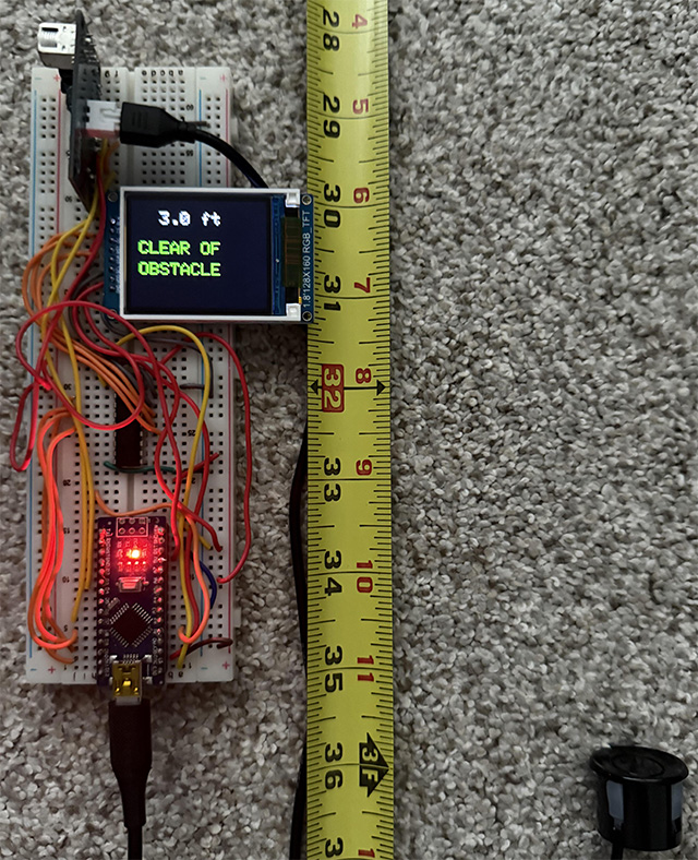
At 3 feet range
After assembling all the hardware on the breadboard and connecting the pins from the Arduino, IC, TFT display, and sensor, I tested the sensor’s proximity readings against a fixed object, such as a wall, using a measuring tape for verification. Based on the sensor output and the programmed logic, the TFT display shows “Clear of obstacle” when the measured distance is between 75 cm (2.46 ft) and 300 cm (9.84 ft). However, the code is designed to switch the display to a blank screen when the distance exceeds 150 cm (4.92 ft), as defined at line 71 in the code.
if (duration == 0 || distance_cm > 150) {
      tft.fillScreen(ST77XX_BLACK);
return;At 2 feet from the obstacle
At 2.0ft, the sensor still appears to provide precise measurements. The code reflects this behavior in lines 120-122. If the distance is greater than or equal to 25 cm (approximately 0.82 ft) and less than 75 cm (approximately 2.46 ft), the display shows the text “CAUTION” in yellow:
else if (distance_cm >= 25 && distance_cm < 75) {
      tft.setTextColor(ST77XX_YELLOW);
      tft.println("CAUTION");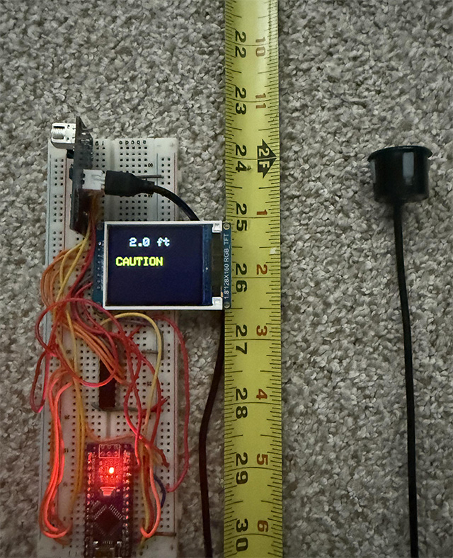
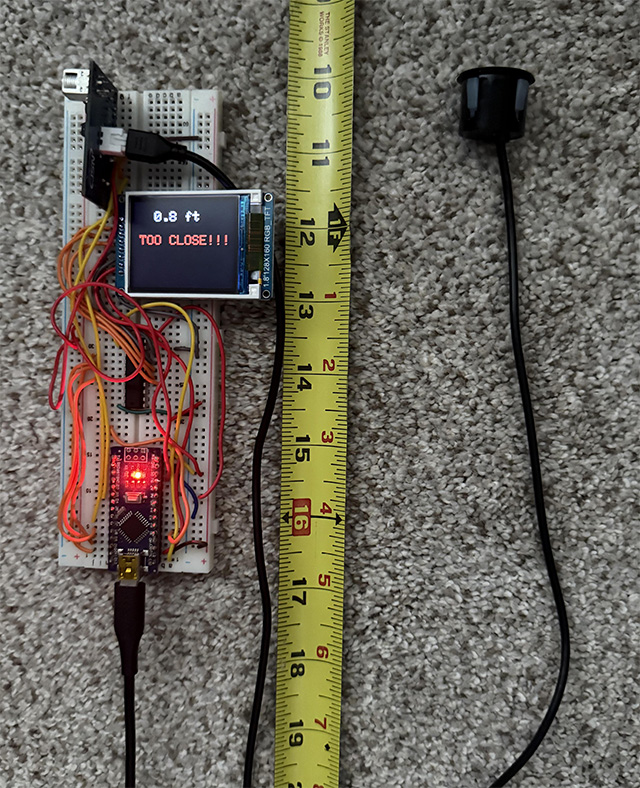
Minimum readable distance from the object
The ultrasonic sensor starts reliably measuring at approximately 25 cm (0.82 feet). When an object is detected closer than 25 cm, the program uses an if statement to display a visual warning:
- Warning remains until the distance increases above 25 cm (0.82 ft), at which point a different message (like “CAUTION” or “CLEAR OF OBSTACLE”) will be shown depending on the new distance.
- If the distance is less than 25 cm, the screen will show “TOO CLOSE!!!” in red text.
 if (distance_cm < 25) {
      tft.setTextColor(ST77XX_RED);
      tft.println("TOO CLOSE!!!");